
Displaying Terrain Model Triangle Edges and Vertices
- In the GeoMedia menus, select Legend > Add Legend Entries.
The Add Legend Entries dialog box appears. - Expand the Terrain Warehouse connection node that contains your TIN terrain model.
- Check the {Your
ModelName}_TriangleVertices feature on. - Check the {YourModelName
}_ TriangleEdges feature on.
The Add Legend Entries dialog box should like as shown below.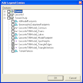
- Click OK.
The triangles and edges are displayed in the active map window.


Now that you can see the triangle vertices and edges, editing the model is so much easier.
- In the GeoMedia menus, select Terrain > Edit > Edit Model Vertices.
The Edit Vertices dockable control is displayed.

- In the Action drop down list, choose Insert.
You are prompted to "Select vertex to insert" in the GeoMedia status bar. - In the Operate on drop down list, choose Individual vertices.
- In the Z field, enter an elevation value e.g. 5000.
- In the map window, click a new vertex point.
A new vertex is created in the map window. You can see the model triangle edges and points dynamically adjust themselves to accomodate the new vertex.
- You can click to insert more vertices.
- If you made a mistake, you can do a mouse right click in the map window.
The Edit Model Vertices context menu pops up.
- Choose Undo to remove the last vertex.
- After you have inserted all the vertices that you want, do a mouse right click in the map window.
- Choose Update Model to save the new vertices permanently into the terrain model.
- Right click and choose Cancel to terminate the command.


- In the Action drop down list, select Move.
The cursor becomes a cross hair cursor. You are prompted to "Select vertex to move". - In the map window, click on a vertex.
The vertex is highlighted and you are prompted to "Select location to move". - Click on the new location in the map window.
The selected vertex is moved to the new location. - In the map window, do a mouse right click and select Update Model.
The changes are saved permanently.
- In the Action drop down list, select Delete.
The cursor becomes a cross hair. You are prompted to "Select vertex to delete". - In the map window, click on a vertex.
The selected vertex is removed and you are prompted to "Select another vertex to delete". - In the map window, right click and choose Update Model.
The changes are saved permanently.
- Click on the Select Tool icon.
- Then click on two or more vertices in the map window. Note that if you want to add to the selection set, then you need to press down the CTRL key on the keyboard while clicking.
- After you are done with selection, in the Action drop down list, select Move.
- In the Operate on drop down list, choose Select set.
You are prompted to "Input X,Y values to move the vertices. - Then key in the relative X and Y offsets in the X and Y fields, e.g. X=500, Y=500.
You are prompted to Click Process Move to move the vertices. - Do a mouse right click in the map window. In the context menu, choose Process Move.
A message box appears showing the number of vertices moved and the number failed. - Click OK.
The vertices in the selection set are moved by the relative X and Y offsets. - In the map window, right click and choose Update Model to save the changes permanently.
You need to activate the Edit Z dockable control toolbar to perform editing on the Z-elevations of the terrain model. Select Terrain > Edit > Edit Z in the GeoMedia menus.
The Edit Z dockable control appears.

Edit Individual Vertex's Z Value
- In the Edit Z control's Applies to drop down list, select Individual vertices.
You are prompted to "Select vertices to edit". - In the control's Operator field, choose None.
- In the control's New Z field, enter an elevation e.g. 6000.
- Click on an existing vertex in the map window.
You are prompted to "Select another vertex or choose 'Edit Vertices' to perform the edit. - Click on additional vertices.
- When you are done, right click in the map window and choose Edit Vertices to perform the edits.
The message box appears showing the number of vertices edited or failed.
- Click OK.
All the selected vertices' elevation values are updated.

- In the control's Applies to drop down list, select Vertices with same Z.
- In the control's Original Z field, enter the Z elevation of the vertices to change e.g. 6000.
- In the control's Operator drop down list, select an operator e.g. +.
- In the control's Operand field, enter the delta value e.g. 500.
The control's New Z field shows the resultant Z value,
e.g. New Z= {Original Z=(6000)}{Operator=(+)}{Operand=(500)}=6500.
- In the map window, right click and choose Edit Vertices.
After processing, the message box showing the number of vertices edited or failed appears. - Click OK.
- In the map window, right click and choose Update Model to save the changes permanently.


No comments:
Post a Comment