
About Geospatial Applications, Intergraph GeoMedia, FME, Visual Studio, gvSIG, Global Mapper, Programming, LiDAR, GIS, Google Maps, SAGA GIS, Android, QGIS
Thursday, October 30, 2008
New Geocoding Engine in GeoMedia 6.1
I am pleased to find out that version 6.1 of Intergraph's line of GeoMedia products including GeoMedia, GeoMedia Professional, WebMap and WebMap Professional have a new address geocoding engine. In previous versions, I could only perform address geocoding with WebMap Location Server which uses the Annotated Centerline Engine (ACE) - that is still available in 6.1 for backward compatibility. The problem with this is that in this region, addresses are better located with postal codes that are tied to so-called address points, not left and right of centerlines. But 6.1 allows geocoding on both point and linear reference data. That means, I can use it here! Yeah.
Tuesday, October 28, 2008
Using the FME GREPPER Factory
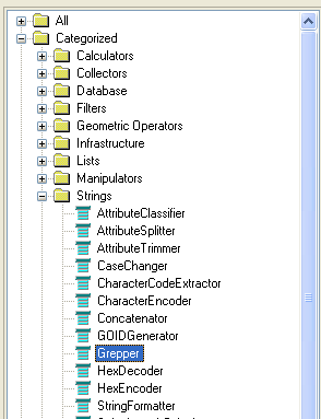
Instead of using the typical FME Workbench factories for filtering records by attributes e.g. AttributeFilter, AttributeClassifier or Tester factories, you could use a powerful regular expression processing factory - the Grepper. As the name suggests, it performs a Unix 'grep' like operation on the input attributes. This factory is available under the Strings category of the FME Workbench as shown in the screen shot below.
The screen shot below shows a typical usage of the Grepper factory in the FME Workbench.
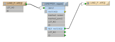
In the example above, the records from LAND_PARCELS feature are filtered through the GREPPER factory. Any unmatched records will be output to the new LAND_PARCELS feature; any matched records to the GREPPER's regular expression will be ignored.
Display the GREPPER's parameters to set the regular expression as shown below.
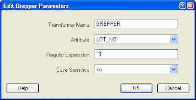
You will have to click the Attribute field and choose an attribute to grep or filter against with the regular expression. In the example above, the field LOT_NO was chosen.
Find Null Strings
If you want to find matches for null strings, i.e. strings with just carriage returns or line feeds, then define the Regular Expression '^$' as shown in the example screen shot above. In plain English, the carat character '^' anchors the expression to the beginning of the string while the dollar '$' character anchors the expression to the end of the string; put together with nothing in between, the expression says 'match all strings with nothing from start to the end of the string'.
Find Strings that Begin with a Character
If you want to find matches for strings that begin with a character such as 'N', then define the Regular Expression '^N'. Some matching strings include the following:
NO12-12345
Nobody
Find Strings that Match a Pattern
The following Regular Expression 'NO\d\d-\d\d\d\d\d' will match any strings with the pattern NOxx-xxxxx where x is any numeric character. Some examples of matching strings include the following:
NO12-12345
Hello World NO12-12345 Hello World
Find Null Numeric Values
The Grepper can be used on numeric fields such as double or integer fields. FME will do a string conversion first before passing the value to the Grepper factory. If you want to filter out any null values in double or integer database fields, you can define the Regular Expression '^$'.
Wednesday, October 22, 2008
Convert Latitude/Longitude to Easting/Northing Coordinates
The CoordSystem object in GeoMedia can perform among other things, coordinate conversion from latitude and longitude to easting and northing using its TransformPoint method. What is not clear from the GeoMedia Object Reference developer documentation is that the latitude and longitude coordinates must be passed in as radians, not degrees; there was no mention of the units at all. I was at a loss for a while wondering why the converted values were incorrect until I found some example code from the Intergraph web site showing the correct usage. In fact, there is also a UnitAndFormatSpec object that comes with the Coordinate System Services (PCSS) that can help you perform the latitude, longitude conversion to radians. Example C# code listing is shown below.
PCSS.CoordSystemsMgr coordSysMgr = null;
PCSS.CoordSystem coordSys = null;
PCSS.UnitAndFormatSpec spec = null;
bool isValid = false;
double x = 104.0, y = 4.0, z = 0.0;
double[] point = { 0, 0, 0 }; //the output easting, northing, height values

//Get a reference to the Coordinate Systems Manager class
//of the GeoMedia workspace
coordSysMgr = (PCSS.CoordSystemsMgr) this._document.CoordSystemsMgr;

//Create an instance of the UnitAndFormatSpec class
spec = (PCSS.UnitAndFormatSpec)this._application.CreateService("UnitAndFormatSpec");

//Convert the longitude to radians
spec.ParseValueString(Intergraph.GeoMedia.PCSS.CSValueStringConstants.csvsLongitude, lng.ToString(), out x);

//Convert the latitude to radians
spec.ParseValueString(Intergraph.GeoMedia.PCSS.CSValueStringConstants.csvsLatitude, lat.ToString(), out y);

//Get a reference to the coordinate system class
coordSys = coordSysMgr.CoordSystem;

//Check first to see if the conversion from latitude, longitude to
// easting, northing is valid
coordSys.IsTransformationValid(Intergraph.GeoMedia.PCSS.CSPointConstants.cspLLU, 1, Intergraph.GeoMedia.PCSS.CSPointConstants.cspENU, 1, out isValid);

//If the conversion is valid, then perform the actual conversion
//from latitude, longitude to easting, northing.
if (isValid == true)
{
   coordSys.TransformPoint(Intergraph.GeoMedia.PCSS.CSPointConstants.cspLLU, 1, Intergraph.GeoMedia.PCSS.CSPointConstants.cspENU, 1, ref x, ref y, ref z);
   point[0] = x;
   point[1] = y;
   point[2] = z;
}
Monday, October 20, 2008
Quick Display of DXF Files in GeoMedia 6.x
By design, the Display CAD Files command in GeoMedia allows you to quickly and easily display CAD files without having to go through the process of defining the CAD Server Schema file; it is difficult for casual users to set up a CAD Server Schema without having much knowledge about the structure and organization of the data in the CAD files. In previous versions, the Display CAD Files command could only handle Microstation design files. But it looks like the command has been enhanced to be able to display AutoCAD DWG/DXF files quickly in version 6.x. So now, AutoCAD users can celebrate!
To start,
If you don't like the compound geometries the command is setting for all the DXF layers or you want to refine the settings made by the Display CAD Files command, then you can modify the CAD Server Schema file generated by the command. Before you can do that, you have to close all open connections to the CAD Server Schema file first.
To start,
- In GeoMedia, select Tools > Display CAD Files.
The Display CAD Files dialog box is displayed.
- In the CAD type drop down list, select AutoCAD.
- In the CAD files folder field, type in or click Browse to define the folder containing your DXF files, e.g. D:\Warehouses\dxf\.
Available DXF files are displayed in the Available files list box.
- In the Available files field, checked on one or more DXF files.
- If you want to associate a coordinate system file for your DXF file(s), then in the Coordinate system file field, type in or click Browse to define the coordinate system file, e.g. D:\Warehouses\dxf\TransverseMercator.csf (optional).
The Display CAD Files dialog box may look like this.
Note: If a coordinate system file is not defined, then GeoMedia will assume the DXF coordinates are in the current workspace's coordinate system. - Click the Advanced tab.
The advanced options are displayed.
- In the Generated CAD server schema file field, type in or click Browse to define the CAD server schema file to be generated, e.g. D:\Warehouses\landuse_dxf.csd. Note: this is optional and you can use the default name if you like.
- In the Connection name field, type in a name, e.g. DXF connection. Note: This is optional and you can use the default name if you like.
- Toggle on Select layers to display. Note: selecting this option will cause the command to scan the DXF file for the layer names. This is preferable to having to figure out by yourself.
The list of DXF layer names is displayed in the Layers list box.
- Toggle on Create a separate legend entry for each selected layer. Note: this is optional but preferable to displaying all DXF graphics as a single GeoMedia feature.

- Click OK.
The selected DXF layer is displayed in the Map Window as a compound geometry.


If you don't like the compound geometries the command is setting for all the DXF layers or you want to refine the settings made by the Display CAD Files command, then you can modify the CAD Server Schema file generated by the command. Before you can do that, you have to close all open connections to the CAD Server Schema file first.
- In Windows Explorer, browse to the CAD Server Schema File folder e.g. D:\Warehouses\ and double click on the CAD Server Schema File, e.g. landuse_dxf.csd.
The Define CAD Server Schema File dialog box appears.
- Select Feature Class > Define Feature Class.
The Define Feature Class dialog box appears.
- In the Feature classes list box, select a feature class, e.g. LAND_USE. Click Edit.
The Edit - Feature XXX dialog box appears.
- In the Geometry type list box, toggle off the CompoundGeometry and TextGeometry. Toggle on the desired type, e.g. AreaGeometry.

- Click OK.
- Click Close.
- Select File > Save.
- Select File > Exit to close the Define CAD Server Schema File application.
- Open up GeoMedia and display the DXF layers.
The DXF feature now has the geometry type of AreaGeometry.


Tuesday, October 14, 2008
Fine tuning of the GeoMedia MapWindow object's height and width
Sometimes I need to define the exact width and height of the GeoMedia map in pixels to control the dimensions of the map view image created by the snap shot function. To do this, a developer can create a custom program to access the MapWindow object and set the width and height properties, as follows:
However, this is not entirely correct because the width and height of the MapWindow object include the Windows border and title bar as shown in the example screen shot below.
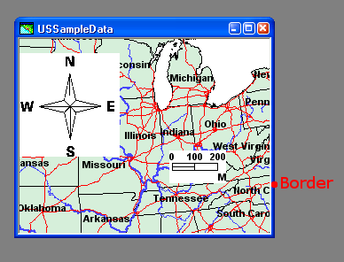
When you do a snap shot of the map window by selecting Edit > Snapshot, an image of the map view is created in the Windows clipboard. The map view image would have a width and height a little less than the width and height you set earlier e.g. 504 pixels by 489 pixels.
To get a map view image with the exact dimensions you want, you will have to add the border width and title bar height to the MapWindow object's width and height properties. An example code listing is shown below.
mapWnd.Width = 512;
mapWnd.Height = 512;
However, this is not entirely correct because the width and height of the MapWindow object include the Windows border and title bar as shown in the example screen shot below.

When you do a snap shot of the map window by selecting Edit > Snapshot, an image of the map view is created in the Windows clipboard. The map view image would have a width and height a little less than the width and height you set earlier e.g. 504 pixels by 489 pixels.
To get a map view image with the exact dimensions you want, you will have to add the border width and title bar height to the MapWindow object's width and height properties. An example code listing is shown below.
MapviewLib.GMMapView mview = null;
double xlo = 0, ylo = 0, zlo = 0, xhi = 0, yhi = 0, zhi = 0; //world
int pixelXlo = 0, pixelYlo = 0, pixelXhi = 0, pixelYhi = 0; //pixels
int mviewWidth, mviewHeight;   //map view dimensions

//Set an initial desired width and height, e.g. 512x512
mapWnd.Width = 512;
mapWnd.Height = 512;

//Get the mapview object in the map window
mview = (MapviewLib.GMMapView)mapWnd.MapView;

//Get the map view object's MBR in real world coordinates
mview.GetRange(ref xlo, ref ylo, ref zlo, ref xhi, ref yhi, ref zhi);

//Convert the real world coordinates to screen pixels
mview.WorldToWindow(xlo, ylo, zlo, ref pixelXlo, ref pixelYlo);
mview.WorldToWindow(xhi, yhi, zhi, ref pixelXhi, ref pixelYhi);

//Calculate the map view objects width and height
mviewWidth = Math.Abs(pixelXhi - pixelXlo);
mviewHeight = Math.Abs(pixelYhi - pixelYlo);

//Adjust the map window object's dimensions by adding
//in the border and title bar's dimensions
mapWnd.Width = (mapWnd.Width - mviewWidth) + mapWnd.Width;
mapWnd.Height = (mapWnd.Height - mviewHeight) + mapWnd.Height;

After this adjustment, the snap shot image will have the correct desired dimensions.
Subscribe to:
Posts (Atom)
