Thursday, May 21, 2009

Close "unclosed" polygons with FME

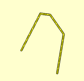
Sometimes I get ASCII text files of polygons but with unclosed vertices. What I mean is that the first point and last point of the polygon in the ASCII file are not the same. An example is shown in the figure below.
When I load this polygon ASCII file into Global Mapper or GeoMedia, the polygon is displayed as an unclosed line string. An example is shown in the figure below.
To close such cases of unclosed polygons, I decided to use FME 2009. Here are the steps I took to form a close polygon from the unclosed polygon ASCII file. There is a LineCloser Transformer in FME that will do the job.
  1. Start up the FME Workbench by selecting Start > All Programs > FME > FME Workbench. Choose to work with the Translation Workspace Wizard.

    The Create Translation Workspace Wizard dialog box appears.


  2. In the text box, choose Comma Separated Value (CSV) as the source data format. Click Next.

    The Locate Source Data page appears.
  3. Browse or type in the location and name of the source ASCII file e.g. C:\Temp\polygon.csv. Click Settings.

    The Input Settings for Comma Separated Value dialog box appears.


  4. In the Separator character drop down list, choose space. Click OK. Click Next.

    The Select Destination Format page appears.


  5. Choose ESRI Shape. Click Next until the Wizard is completed.

    The Workbench is filled in with the source and destination datasets.

  6. In the FME Workbench, add in the 2DPointAdder, PointConnector, LineCloser Transformers. Connect them to the source and destination datasets as shown in the figure below.

  7. Open up the 2DPointAdder Parameters.

  8. In the X Value drop down list, choose col0. In the Y Value drop down list, choose col1. Click OK.

  9. Open up the destination dataset Feature Type Properties.

  10. In the Allowed Geometries drop down list, choose shape_polygon. Click OK.
  11. Run the translation.

    The unclosed polygon ASCII file is transformed to a closed polygon in Shapefile format.

Import Text File as area polygons in Global Mapper

Sometimes I have ASCII text files that contain XY coordinates defining the outline of polygons. An example is my polygoncoords.txt file shown in the figure below. Typically it has the polygon vertices listed from the first point to the last point, with the last point having the same XY coordinates as the first point. 
It is not clear how you can load this kind of polygon ASCII text file in Global Mapper as area geometry features. If you use the Global Mapper's Open Generic ASCII Text File command, it will be loaded as a line vector feature. I had to dig around before I found out how to load it as a polygon vector feature. Here is how I did it.
  1. Open up the polygon ASCII text file in your favorite text editor and add in the following line at the top:

    CLOSED = YES


    Note: I also added NAME=My Polygon in the example above. This line simply tells Global Mapper to create and display the label "My Polygon".

  2. Close and save the text file.

  3. In Global Mapper, select File > Open Generic ASCII Text File(s).

    The Open dialog box appears.


  4. In the Open dialog box, browse or type in the polygon ASCII text file in the File name field. Click Open.

    The Generic ASCII Text File Import Options dialog box appears.


  5. In the Generic ASCII Text File Import Options dialog box, ensure that the Point, Line, and Area Features option is on. Click OK

    The Select Projection for dialog box appears.


  6. Define an appropriate coordinate system. Click OK.

    The area vector feature is created and displayed in Global Mapper.


  7. If you use the Tools > Feature Info tool and click on the polygon, the polygon is highlighted as shown in the figure below. Note that the Feature Information dialog is showing that the Feature Type is an area type. 

Friday, May 15, 2009

Create labels in Global Mapper 10

I wanted to display the shape file's attribute values as labels in the Global Mapper's map display and I had some difficulty in figuring out how to do it. For instance, I have these grid shapes that I wanted to label with the grid shape's attribute field GRIDAB value on the screen as shown in the figure below. 
These steps are how I got Global Mapper to display the attributes as labels.
  1. In Global Mapper 10, select Tools > Control Center.

    The Overlay Control Center dialog box appears.


  2. In the Overlay Control Center dialog box, select the overlay feature you want to label, e.g. grid.shp.

  3. Click Options.

    The Vector Options dialog box appears.


  4. Toggle on Use Selected Attribute Value for Name. In the drop down list, choose the attribute field for labelling e.g. GRIDAB.

  5. Click OK.

    The vector overlay is labeled with the attribute values.

Note that you can also string more than one attribute fields to form the labels.  In the Vector Options dialog box, toggle on Use Multiple Attributes for Name


This will bring up the Attribute Naming Setup dialog box. Simply select the attributes you want under Available Attributes then click Add to form the Attributes in Name on the right side. You can choose the separator between the attribute values in the box as shown below. 

Click OK. This will create the labels as defined in the map display as shown below. 

Thursday, May 7, 2009

Connecting and display a text file in GeoMedia

It is easy for GeoMedia to connect and display the contents of text files. The hard part is defining the format of the text file and I have covered that in my previous post. To connect to a CSV text file as shown in the screen shot below, simply do the following steps:
  1. In GeoMedia, select Warehouse > New Connection.

    The New Connection dialog box appears.


  2. Under Connection type, choose Text File.

  3. In the Connection name field, type in a connection name (optional) or use the default. 

  4. In the Input text file field, click Browse. 

    The Select an Input Text file dialog box appears.

  5. In the File name field, select or key in the text file name. Click Open.

  6. In the Text format definition field, click Browse.

    The Select a Text format definition file dialog box appears.


  7. Select or key in the name of the text file server format definition file you have defined earlier ( as created in my previous post). Click Open.

    The New Connection dialog box should look similar to this.


  8. Click OK.

    The text file connection is created and opened.
To display the text file contents, you can use the standard GeoMedia commands such as New Data Window as shown below.
  1. Select Window > New Data Window.


  2. Expand the text file connection and select a text feature. Click OK.

    The text file contents is displayed in the Data Window.

Defining a Text File Server format file for GeoMedia

GeoMedia can read text files (such as the simple CSV file shown in the screenshot below) directly through the Text File Connection. 
But before you can connect to the text file, you have tell GeoMedia how the text file is formatted or structured i.e. you have to define the name of the field, the data type of the field, geometry type if any etc. This post describes the steps to create a text file server format using GeoMedia's Define Text File Server Format File Utility.
  1. On the Windows desktop, select Start > All Programs > GeoMedia > Utilities > Define Text File Server Format File.

    The Define Text File Server Format dialog box appears.


  2. Select File > New.

    The New dialog box appears.

  3. Choose normal.tfd. Click New.

    The Define Text File Server Format - File Type Definition dialog box appears.


  4. Click Browse. Note: we want to see a sample of our text file to help in the definition process. 

    The TFD Open Text File dialog box appears.


  5. Browse and select the text file we want to read in GeoMedia, e.g. mytextfile.csv. Click Open

    The text file is previewed in the Text file preview box.


  6. In the Geometry type drop down list, choose None.

    Note: if your text file contains point geometry records, then choose Point. Later you have to define the X and Y geometry fields. In this example, I'll go with no geometry


  7. If your text file has a header row, enter 2 in the Start row field to skip the header row. 

    The Define Text File Server Format - File Type Definition dialog box may look like this at this point.


  8. Click Next

    The Define Text File Server Format - Delimited Data Definition page appears.

  9. If the data is comma delimited, toggle on Comma.


  10. Click Next.

    The Define Text File Server Format - Geometry Definition - Points page appears. Note that the first preview column is marked with a check icon

  11. In the attribute name field, clear the text "skip" and enter a meaningful name for the field, e.g. id. Click Set attribute definition.

  12. Click the second column header. In the attribute name field, clear "skip" and enter the field name e.g. Easting. In the attribute data type field, choose Double. Click Set attribute definition

  13. Repeat the previous step 12 for the remaining columns, if any.

  14. Click Finish.

    The Message "Do you want to save the changes you made to 'Untitled.tfd'?" appears.

  15. Click Yes.


  16. In the File name field, enter a file name. Click Save.

    The Text file server format definition is created and can be used when connecting to this text file in GeoMedia.